
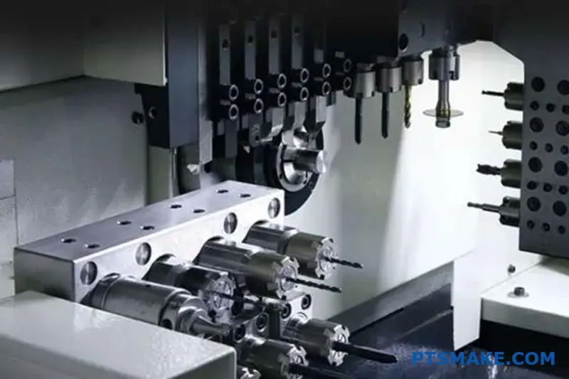
A finished Swiss-machined part can look deceptively simple: a small shaft, pin, connector, sleeve, or threaded component that fits in the palm of a hand. Inside the machine, however, that part passes through a closely coordinated sequence. Bar stock must feed correctly through the guide bushing, cutting tools must work near the support point, live tools may add cross-holes or flats, and a sub-spindle may receive the component before cutoff. Programming, chip control, deburring, and inspection connect these operations into one production cycle.
Understanding that sequence helps engineers prepare clearer drawings and helps buyers evaluate a supplier’s process plan. This article follows the part from incoming bar stock to final inspection, showing where control matters and why the machine name alone does not guarantee a reliable result.
The Cycle Begins Before the Bar Enters the Machine
The first cutting tool cannot correct every problem in the starting material. Alloy, temper, bar diameter, straightness, and surface condition all influence how the stock feeds and how it behaves near the cutting zone.
Bar Stock Must Suit the Guide-Bushing Strategy
In a guide-bushing setup, the bar passes through a close-fitting support while the cutting tools work nearby. The stock must move without binding, yet remain supported well enough to limit unwanted movement. If bar diameter varies too much or the stock is not sufficiently straight, feeding and support may become less predictable.
The correct stock specification depends on the machine, guide bushing, material, part diameter, and surface requirements. There is no single bar tolerance that applies to every Swiss CNC machining project. The process review should establish:
- Alloy and temper
- Starting diameter and available allowance
- Bar straightness and surface condition
- Material certification or traceability requirements
- Whether a guide-bushing or guide-bushing-free approach is planned
For a broader explanation of machine selection, suitable geometry, and purchasing considerations, engineers can consult this Swiss machining guide for engineers and buyers.
The Sliding Headstock Changes Where Cutting Happens
The defining motion of a cnc swiss lathe is easier to understand when viewed from the cutting point. Bar stock moves through the guide bushing as the sliding headstock travels along the machine axis. Turning tools remain close to the location where the bar is supported.
The Stock Moves While the Tool Stays Near the Support
On a conventional lathe, a longer section can extend from the chuck or collet as the tool travels along it. In a swiss type cnc lathe, the work is generally presented through the guide bushing so the active cut occurs near the support.
The relationship can be summarized simply:
- Short unsupported length
- → lower deflection risk
- → more stable contact between tool and material
- → better control of slender features
This does not mean every small part needs a Swiss machine. Short, rigid components with uncomplicated geometry may be produced efficiently by conventional turning. The drawing, quantity, material, and required operations should determine the route.
Programming Coordinates More Than a Single Toolpath
Swiss CNC programming may need to coordinate the main spindle, sliding headstock, live tools, sub-spindle, cutoff tool, and bar-feeding sequence. The program defines when each machine element can move and which operations may occur at the same time.
Main and Sub-Spindle Operations Need a Shared Timeline
The main spindle normally controls the front portion of the part while the sub-spindle prepares to receive it. Depending on the component, live tools may drill or mill while turning tools work elsewhere. The program must prevent one operation from blocking another and must allow enough clearance for every tool.
A practical sequence might include:
- Feed the bar to the programmed starting position.
- Turn the front diameters and shoulders.
- Drill, bore, thread, or add live-tool features.
- Bring the sub-spindle into the transfer position.
- Grip the component before or during cutoff.
- Move the separated part to the back-working station.
- Finish the cutoff side and release the completed part.
Front-End Turning Establishes the Primary Geometry
The Swiss CNC machining process begins forming the component’s main rotational geometry before cutoff. Depending on the drawing, swiss turning may produce external diameters, shoulders, grooves, chamfers, bores, and threads.
Tool Order Affects Stability
Removing too much supporting material too early can make a slender feature harder to control. The process may therefore leave temporary support, separate roughing from finishing, or complete the most sensitive diameter while the surrounding geometry remains rigid.
Tool order also affects burr location and inspection access. A later drill may break into an earlier bore, while a thread tool may create a burr near a sealing face. The process plan should consider how one operation changes the conditions for the next.
Live Tooling Adds Features Beyond the Main Axis
Modern swiss turning centers can combine rotational cutting with drilling and milling. This allows swiss turn machining to produce features that would otherwise require a separate machine or fixture.
| Part Feature | Likely Operation | Primary Control Point |
| Main diameter | Turning | Size, roundness, and surface condition |
| Cross-hole | Live-tool drilling | Position relative to the main axis |
| Flat or slot | Milling | Orientation, depth, and burr control |
| External thread | Thread turning | Thread form and starting condition |
| Back feature | Sub-spindle machining | Transfer position and overall length |
Completing more features in one cycle can reduce handling, but it is not automatically the best plan. The supplier must consider tool access, available stations, cycle balance, inspection, and the consequences of combining too many operations in one setup.
The Sub-Spindle Takes Over Before the Part Is Released
The transfer from main spindle to sub-spindle is one of the most important stages in the Swiss CNC machining process. It allows the cutoff side to be finished without allowing the part to fall loose and then be manually reoriented.
Pickoff Preserves Control During Transfer
The sub-spindle approaches the partly completed component and grips it at a defined position. Cutoff then separates the part from the remaining bar. Grip location, transfer timing, and cutoff allowance affect overall length and the material available for back working.
This transfer connects front-end machining with the remaining back-working operations.
Back Working Completes the Cutoff Side
After transfer, the sub-spindle presents the rear of the part to back-working tools. Depending on the drawing, these tools may:
- Face the cutoff surface
- Add a chamfer
- Drill or bore a rear feature
- Cut or finish a thread
- Remove a cutoff remnant
- Complete a rear locating surface
Not every part needs extensive back working. The value comes from completing functionally necessary features while the part remains under controlled location.
A Finished Cycle Still Requires Deburring and Inspection
When the component leaves the machine, cutting is complete but manufacturing may not be. CNC swiss screw machine parts can contain intersecting holes, thread starts, small grooves, and cutoff edges that need careful review.
Burr Control Begins with Operation Planning
Deburring should not be left as an undefined final task. The process should identify where burrs are likely to form, which edges have functional requirements, and which removal method will avoid changing small features.
Cross-hole intersections and thread entries deserve particular attention. An aggressive manual method may remove the burr but also round an edge or alter a feature that the drawing expects to remain controlled.
Inspection Must Follow Function
Inspection for swiss machined parts may include diameter, length, concentric relationships, thread condition, cross-hole position, surface finish, and visual burr checks. The actual plan must follow the drawing rather than a generic checklist.
Measurement should also reflect the production stage. A dimension checked before deburring, cleaning, heat treatment, or coating may not represent the final delivery condition.
Repeat Production Tests the Whole Manufacturing System
The first accepted part validates the initial setup. Buyers reviewing Yueyi Precision’s precision manufacturing capabilities should also consider how the process is controlled after tools wear, a new bar is loaded, production restarts, or the program revision changes.
Stable repeat production connects:
controlled material + verified program + managed tooling + relevant inspection
Useful production records may identify the material batch, drawing revision, program version, important tool changes, inspection results, and approved deviations. The purpose is to preserve the conditions that produced the accepted component.
The Best Swiss Cycle Is Built Around the Drawing
Reliable cnc swiss precision machining does not come from the equipment name alone. It comes from matching the bar, guide-bushing strategy, tool sequence, programming, spindle transfer, burr control, and inspection plan to the drawing.
Engineers can improve the result by identifying functional datums, critical feature relationships, material condition, and final delivery requirements. Buyers can improve supplier evaluation by asking how the component moves from bar stock to finished part and where the process detects change.
The best cycle is not necessarily the one with the most simultaneous operations. It is the one that controls the important features, avoids unnecessary transfers, and remains understandable when the first setup becomes repeat production.


